
Twombolt info and instructions

Download the Full Manual (PDF – 762kb)
TWOMBOLT CRANKS SHIPPING
Our update to the Wombolt crankset is on its way to shops and distributors. Twombolts (Two+Wombolt) are available now in fluorescent red, white and black. We have RHD-175 at the moment, with LHD and other sizes following soon.
The new features for the crank are as follows:
– Updated mating arm lug for improved fit and increased durability.
– All-new cluster design that optimizes the arm’s interface, simplifies assembly, and makes use of a durable AND replaceable elastic retainer band.
– Greatly improved overall function and performance proven both in the lab and during extensive long-term riding.
– 2 lbs. 2.5 oz. / 978g (with Mid BB). 1 lb. 13.5 oz. / 836g (without BB).
New Twombolt mating arms and wedge clusters are compatible with existing Wombolt drive arms (click to enlarge).


NEW INSTRUCTION SHEETS (CLICK TO ENLARGE):

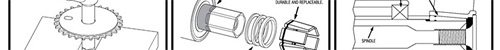

1. Slide the sprocket onto the spindle.

2. Lubricate the sprocket bolt threads.

3. Start the sprocket bolt in the crank arm threads. Do not fully tighten it down. This step helps to keep the sprocket properly oriented in the following step.

4. To seat the sprocket, place the spindle in a bench vise and gently tap the crank arm using a hard rubber mallet. Use wood to protect the sprocket. Snug the bolt into place after fully seating the sprocket.

5. Check for the proper bottom bracket spacer tube size by holding the assembly up to the frame’s bottom bracket shell.

6. Prep the bottom bracket shell with light grease.

7. Use a bottom bracket press to fully seat the bearings. If a press is not a available, a make-shift version can be made by using two plates (old wood, sprockets, bearings, etc.) a bolt, a nut, etc.

8. Note the fully visible and properly positioned spacer tube in this photo. This spacer tube should always be used.

9. With a 6mm (1/4″) sprocket and a Mid BB, use one of the thick (3mm) spindle washers to achieve proper chain alignment. Adjust this spacing as necessary to accommodate any variation with the BB and sprocket size.

10. Slide the spindle all the way through the bottom bracket bearings. The spindle should slide through with only a very gentle amount of force if the bearings have been fully seated in the frame’s BB and are manufactured to the proper 22mm inner diameter specification.

11. Note the thick spindle washer (3mm) between the 6mm sprocket and Mid BB.

12. Slide the included spindle washers on. The spindle washer diameter allows the crank arm to move past the wedge cluster, so be sure to back the wedges up against at least one of them.

13. Use enough washers to cover the spindle’s “step” between round and hexagonal by at least 1mm.

14. Only the spindle’s hexagonal flats should be visible after the washers are installed.

OPTIONAL: Most aluminum dust covers can be used. However, you should be sure to use at least one of the included spindle washers between the dust cover and the wedge cluster. If there is not enough room for this, stick with using the washers alone.

15. A gentle amount of force will allow the new elastic cluster band to expand for installation on the spindle.

16. Slide the wedge cluster into place.

17. Flip each individual wedge up and apply anti-seize to the spindle’s hex flats.

18. Lube the spindle threads.

19. Lube the wedge faces that contact the arm.

20. Smooth the anti-seize over the entire wedging face.

21. Push the crank arm onto the wedges.

22. Use anti-seize on the lip where the locking bolt contacts the crank arm.

23. Lube the lock bolt threads.

24. Tighten the lock bolt as needed with an ordinary “long” 6mm hex key wrench (shown).

25. Check the sprocket bolt tightness.

26. The cranks should spin freely in the bottom bracket if you’ve done everything properly. For additional tips and information, please check the instruction sheet included with the crankset.

